
This article was originally a set of notes written while reading QEMU's PCI implementation. The structure is not meant to be a complete PCI specification. The goal is more practical: start from PCI address-space concepts, follow how QEMU creates PCI buses and devices, then trace how an MMIO access from the guest finally reaches a device callback in QEMU.
1. PCI Device Address Space Basics
A PCI device uses BARs, or Base Address Registers, to describe the address ranges it needs. A standard PCI device can have up to six BARs, BAR0 through BAR5. Each BAR may map to one of two types of address space:
- Memory Space, usually called MMIO, or memory-mapped I/O.
- I/O Space, usually called PMIO, or port-mapped I/O.
BARs are used both to tell the system how much memory or I/O space a device needs and to hold the assigned address of the device registers.
One way to think about the PCI bus is to compare it with an internal highway system:
- The PCI bus is the main road.
- PCI devices, such as network cards, graphics cards, and sound cards, are buildings along the road.
- The PCI host bridge is the entrance that connects the CPU side to the PCI bus.
- A BAR is the address plate of a building.
1.1 MMIO
In MMIO, memory and I/O devices share the same physical address space.
The CPU issues a memory access instruction, such as mov, load, or store.
    |
    v
The chipset or northbridge decodes the address on the address bus.
    |
    v
Is this address RAM or a device?
    |-- RAM address range    -> route to the memory controller -> DRAM
    `-- Device address range -> route to the PCI bus           -> device registers
The key points are:
- The CPU uses normal memory access instructions, such as
mov [addr], value. - There is no dedicated I/O instruction involved.
- Device registers are mapped into a region of the physical address space.
- When these addresses are accessed, the chipset routes the request to the device instead of to RAM.
1.2 PMIO
PMIO uses a separate I/O address space and usually relies on special CPU instructions such as in and out.
The CPU issues a dedicated I/O instruction, such as in or out.
    |
    v
The access uses a separate I/O address space, usually 0-65535 on x86.
    |
    v
The chipset detects an I/O cycle.
    |
    v
The request is routed to the PCI device.
The device has an address space separate from memory. To isolate the two spaces, the platform can expose an I/O signal on the CPU physical interface or provide a dedicated I/O bus. On x86, this is why port I/O exists as a distinct mechanism.
Each BAR can be configured as:
    |-- MMIO space: points to a memory address, such as 0xFEBC0000
    `-- PMIO space: points to an I/O port, such as 0xC050
2. PCI Initialization in QEMU
The following flow shows the high-level path used by a typical x86 PC machine in QEMU. The exact machine type may differ, but the main relationships between memory regions, the PCI host bridge, the root bus, and PCI devices are the same.
QEMU startup: main()
    |
    v
Machine initialization: pc_init1()
    hw/i386/pc_piix.c
    |
    v
1. Initialize memory regions
   - system_memory
   - system_io
   - pci_memory

   memory_region_init(pci_memory, NULL, "pci", UINT64_MAX)
    |
    v
2. Create the PCI host bridge
   phb = qdev_new(TYPE_I440FX_PCI_HOST_BRIDGE)

   Set property links:
   - RAM_MEM    -> ram_memory
   - PCI_MEM    -> pci_memory
   - SYSTEM_MEM -> system_memory
   - IO_MEM     -> system_io
    |
    v
3. Realize the PCI host bridge
   sysbus_realize_and_unref(SYS_BUS_DEVICE(phb))

   Calls i440fx_pcihost_realize()
   hw/pci-host/i440fx.c
    |
    v
4. Map PCI configuration-space ports
   - 0xCF8: PCI configuration address port, conf_mem
   - 0xCFC: PCI configuration data port, data_mem

   memory_region_add_subregion(io_memory, 0xcf8, conf_mem)
   memory_region_add_subregion(io_memory, 0xcfc, data_mem)
    |
    v
5. Create the PCI root bus
   b = pci_root_bus_new(dev, NULL, pci_address_space,
                        io_memory, 0, TYPE_PCI_BUS)

   Calls pci_root_bus_internal_init()
   hw/pci/pci.c
    |
    v
6. Initialize the PCIBus structure
   - bus->address_space_mem = mem
   - bus->address_space_io  = io
   - bus->flags |= PCI_BUS_IS_ROOT
   - bus->devices[256] = { NULL }

   pci_host_bus_register(parent)
    |
    v
7. Create the i440FX PCI device at device number 0
   d = pci_create_simple(b, 0, TYPE_I440FX)

   - Vendor ID: 0x8086, Intel
   - Device ID: 0x1237, 82441
   - Class: PCI_CLASS_BRIDGE_HOST
    |
    v
8. Set up memory mappings
   - PCI hole, usually around 3.5 GB to 4 GB
   - SMRAM region
   - PAM, programmable attribute map

   pc_pci_as_mapping_init(system_memory, pci_address_space)
    |
    v
9. Set up interrupt routing
   pci_bus_map_irqs(pcibus, pc_pci_slot_get_pirq)

   PCI INTx lines A/B/C/D are mapped to PIRQ lines.
    |
    v
10. Create southbridge PCI devices, such as PIIX3 or PIIX4
    pci_dev = pci_new_multifunction(-1, TYPE_PIIX3)

    This normally includes:
    - ISA bridge
    - IDE controller
    - optional USB controller
    - ACPI and power management
    |
    v
11. Realize PCI devices
    pci_realize_and_unref()
    pci_qdev_realize() -> PCIDeviceClass->realize()

    - Allocate configuration space, 256 or 4096 bytes
    - Initialize BARs
    - Set up interrupts
    - Insert the device into bus->devices[devfn]
    |
    v
12. Create other PCI devices
    - VGA
    - network devices, such as e1000, rtl8139, or virtio-net
    - storage controllers, such as virtio-blk or NVMe
    - audio devices, and so on

    These devices are created either by the default machine configuration
    or by command-line options such as -device.
    |
    v
13. PCI initialization is complete
    - The PCI bus is ready.
    - The guest can enumerate devices through 0xCF8 and 0xCFC.
    - Device MMIO and PMIO regions are mapped into the address space.
    - Interrupt routing is configured.
3. PCI Device Registration
This section uses QEMU's edu PCI device as the example. edu is the official educational PCI device provided by QEMU. It is meant to help students and developers understand how to write a device driver.
The registration and realization flow is:
QEMU starts
    |
    v
1. The type system is initialized through DEFINE_TYPES.
    |
    v
2. The device class is registered through edu_class_init.
    |
    v
3. The user creates the device, for example with -device edu.
    |
    v
4. The object instance is initialized through edu_instance_init.
    |
    v
5. The device is realized through pci_edu_realize.
    |
    v
6. The device becomes available to the guest.
3.1 EDU Device Model
The EDU device gives the guest an MMIO register interface, DMA behavior, and interrupt behavior. A guest driver can then access it like a real PCI device.
QEMU virtual machine
|
`-- Guest Linux
    |
    `-- Student-written EDU driver
        |
        |  MMIO / DMA / IRQ
        v
        EDU virtual PCI device
        implemented by hw/misc/edu.c
The EDU device contains four teaching modules:
1. Basic MMIO reads and writes
   - device identification register, 0x00
   - liveness-check register, 0x04
   - goal: basic register access

2. Asynchronous computation plus interrupts
   - factorial computation, 0x08
   - status register, 0x20
   - interrupt status, 0x24
   - goal: asynchronous work and interrupt handling

3. Interrupt control
   - trigger interrupt, 0x60
   - clear interrupt, 0x64
   - goal: interrupt management, INTx and MSI

4. DMA transfer
   - DMA source address, 0x80
   - DMA destination address, 0x88
   - DMA count, 0x90
   - DMA command, 0x98
   - goal: DMA programming and memory management
3.2 Defining the Device Type
static const TypeInfo edu_types[] = {
    {
        .name          = TYPE_PCI_EDU_DEVICE,
        .parent        = TYPE_PCI_DEVICE,
        .instance_size = sizeof(EduState),
        .instance_init = edu_instance_init,
        .class_init    = edu_class_init,
        .interfaces    = (const InterfaceInfo[]) {
            { INTERFACE_CONVENTIONAL_PCI_DEVICE },
            { },
        },
    }
};

DEFINE_TYPES(edu_types)
The important fields are:
#define TYPE_PCI_EDU_DEVICE "edu"

.name          = "edu"                 // device type name, used by -device edu
.parent        = TYPE_PCI_DEVICE       // inherits from PCIDevice
.instance_size = sizeof(EduState)      // memory size of each instance
.instance_init = edu_instance_init     // instance initializer
.class_init    = edu_class_init        // class initializer
.interfaces    = CONVENTIONAL_PCI_DEVICE
3.3 Class Initialization
static void edu_class_init(ObjectClass *class, const void *data)
{
    DeviceClass *dc = DEVICE_CLASS(class);
    PCIDeviceClass *k = PCI_DEVICE_CLASS(class);

    k->realize = pci_edu_realize;
    k->exit = pci_edu_uninit;
    k->vendor_id = PCI_VENDOR_ID_QEMU;
    k->device_id = 0x11e8;
    k->revision = 0x10;
    k->class_id = PCI_CLASS_OTHERS;
    set_bit(DEVICE_CATEGORY_MISC, dc->categories);
}
This fills the PCIDeviceClass with the callbacks and configuration-space identity visible to the guest:
k->realize = pci_edu_realize;       // device realize function, similar to init
k->exit    = pci_edu_uninit;        // device cleanup function

k->vendor_id = PCI_VENDOR_ID_QEMU;  // vendor ID, visible in lspci
k->device_id = 0x11e8;              // device ID
k->revision  = 0x10;                // revision
k->class_id  = PCI_CLASS_OTHERS;    // PCI class
3.4 Instance Initialization
static void edu_instance_init(Object *obj)
{
    EduState *edu = EDU(obj);

    edu->dma_mask = (1UL << 28) - 1;
    object_property_add_uint64_ptr(obj, "dma_mask",
                                   &edu->dma_mask, OBJ_PROP_FLAG_READWRITE);
}
This is per-object initialization. It initializes the DMA mask and exposes it as a configurable object property.
3.5 Device Realization
The core device setup happens in pci_edu_realize:
static void pci_edu_realize(PCIDevice *pdev, Error **errp)
{
    EduState *edu = EDU(pdev);
    uint8_t *pci_conf = pdev->config;

    pci_config_set_interrupt_pin(pci_conf, 1);

    if (msi_init(pdev, 0, 1, true, false, errp)) {
        return;
    }

    timer_init_ms(&edu->dma_timer, QEMU_CLOCK_VIRTUAL, edu_dma_timer, edu);

    qemu_mutex_init(&edu->thr_mutex);
    qemu_cond_init(&edu->thr_cond);
    qemu_thread_create(&edu->thread, "edu", edu_fact_thread,
                       edu, QEMU_THREAD_JOINABLE);

    memory_region_init_io(&edu->mmio, OBJECT(edu), &edu_mmio_ops, edu,
                          "edu-mmio", 1 * MiB);
    pci_register_bar(pdev, 0, PCI_BASE_ADDRESS_SPACE_MEMORY, &edu->mmio);
}
The important steps are:
// 1. Configure the PCI interrupt pin, INTA#.
pci_config_set_interrupt_pin(pci_conf, 1);

// 2. Initialize MSI support.
// Parameters: device, offset, vector count, 64-bit support, per-vector masking.
msi_init(pdev, 0, 1, true, false, errp);

// 3. Initialize the DMA timer, used to emulate DMA latency.
timer_init_ms(&edu->dma_timer, QEMU_CLOCK_VIRTUAL, edu_dma_timer, edu);

// 4. Create a background thread for factorial computation.
qemu_thread_create(&edu->thread, "edu", edu_fact_thread, edu, ...);

// 5. Create the MMIO MemoryRegion.
memory_region_init_io(
    &edu->mmio,       // MemoryRegion object
    OBJECT(edu),      // owner
    &edu_mmio_ops,    // read/write callbacks
    edu,              // opaque pointer passed to callbacks
    "edu-mmio",       // name
    1 * MiB           // size
);

// 6. Register the MemoryRegion as PCI BAR0.
pci_register_bar(
    pdev,
    0,
    PCI_BASE_ADDRESS_SPACE_MEMORY,
    &edu->mmio
);
For an MMIO read callback, the prototype is:
uint64_t (*read)(void *opaque, hwaddr addr, unsigned size);
The parameters mean:
opaquepoints to the device state structure, in this caseEduState.addris the offset relative to the start of the MemoryRegion.sizeis the width of this read.
The return value is the data read from the specified MMIO address. In practice, each read returns at most 8 bytes because QEMU is emulating the result of a CPU memory-load instruction, and a single x86-64 instruction normally reads at most 8 bytes for this kind of general-purpose access.
3.6 Read and Write Operation Callbacks
static const MemoryRegionOps edu_mmio_ops = {
    .read = edu_mmio_read,
    .write = edu_mmio_write,
    .endianness = DEVICE_NATIVE_ENDIAN,
    .valid = {
        .min_access_size = 4,
        .max_access_size = 8,
    },
    .impl = {
        .min_access_size = 4,
        .max_access_size = 8,
    },
};
For a write, the simplified call chain is:
Guest: mov [0xFEBF1000], 1337
    |
    v
VM exit
    |
    v
KVM captures the access.
    |
    v
The request is returned to QEMU.
    |
    v
QEMU's memory system looks up the target MemoryRegion.
    |
    v
The address resolves to edu->mmio.
    |
    v
QEMU calls edu_mmio_write(edu, 0x00, 1337, 4).
    |
    v
The device model handles the write.
4. MMIO Read Call Chain
This section traces an MMIO read from the guest instruction to the final device callback.
4.1 Complete Flow
Guest OS
|
|  A driver or application reads from the mapped MMIO page:
|
|      uint32_t val = *(uint32_t *)(mmio_mem + 0x08);
|
|  CPU executes:
|      MOV EAX, [0xFEBF1008]
|      This is EDU BAR0 + 0x08.
|
v
VM exit, caused by an EPT violation or MMIO access
|
v
Linux host kernel
|
|  KVM detects that the guest accessed a device address.
|  It fills the shared kvm_run structure:
|
|      run->exit_reason    = KVM_EXIT_MMIO
|      run->mmio.phys_addr = 0xFEBF1008
|      run->mmio.len       = 4
|      run->mmio.is_write  = 0
|
|  KVM_RUN returns to userspace.
|
v
QEMU process
|
|  kvm_cpu_exec()
|    -> kvm_vcpu_ioctl(cpu, KVM_RUN, 0)
|    -> switch (run->exit_reason)
|    -> case KVM_EXIT_MMIO
|    -> address_space_rw(&address_space_memory,
|                        run->mmio.phys_addr,
|                        attrs,
|                        run->mmio.data,
|                        run->mmio.len,
|                        run->mmio.is_write)
|    -> address_space_read_full()
|    -> address_space_to_flatview()
|    -> flatview_read()
|    -> flatview_translate()
|    -> flatview_read_continue()
|    -> flatview_read_continue_step()
|    -> memory_region_dispatch_read()
|    -> memory_region_dispatch_read1()
|    -> access_with_adjusted_size()
|    -> memory_region_read_accessor()
|    -> tmp = mr->ops->read(mr->opaque, addr, size)
|    -> edu_mmio_read(edu, 0x08, 4)
|    -> switch (addr) { case 0x08: return edu->fact; }
|    -> the value is returned layer by layer into run->mmio.data
|
v
VM enter
|
v
The guest continues execution, and the read value is injected into EAX.
4.2 Sequence Diagram
Guest vCPU          KVM kernel          QEMU userspace          EDU device
    |                   |                     |                     |
    | MOV [0xFEBF1008]  |                     |                     |
    |------------------>|                     |                     |
    |                   | EPT violation       |                     |
    |                   | device address      |                     |
    |                   |                     |                     |
    |                   | fill kvm_run        |                     |
    |                   | exit_reason=MMIO    |                     |
    |                   |                     |                     |
    |                   | ioctl returns       |                     |
    |                   |-------------------->|                     |
    |                   |                     | address_space_rw    |
    |                   |                     | flatview_translate  |
    |                   |                     | find MemoryRegion   |
    |                   |                     |                     |
    |                   |                     | dispatch_read       |
    |                   |                     |-------------------->|
    |                   |                     |                     | edu_mmio_read
    |                   |                     |                     | switch(0x08)
    |                   |                     |                     | return fact
    |                   |                     |<--------------------|
    |                   |                     |                     |
    |                   | write data to       |                     |
    |                   | run->mmio.data      |                     |
    |                   | KVM_RUN ioctl       |                     |
    |                   |<--------------------|                     |
    |                   |                     |                     |
    |                   | VM enter            |                     |
    |                   | inject result       |                     |
    |<------------------| into EAX            |                     |
    | continue          |                     |                     |
4.3 Stage 1: KVM Captures the MMIO Access
The path starts in accel/kvm/kvm-all.c:
int kvm_cpu_exec(CPUState *cpu)
{
    struct kvm_run *run = cpu->kvm_run;  // shared memory page

    do {
        // Enter the guest.
        run_ret = kvm_vcpu_ioctl(cpu, KVM_RUN, 0);

        // Return here after the guest causes a VM exit.
        switch (run->exit_reason) {
        case KVM_EXIT_MMIO:
            address_space_rw(&address_space_memory,
                             run->mmio.phys_addr,  // 0xFEBF1008
                             attrs,
                             run->mmio.data,       // data buffer
                             run->mmio.len,        // 4 bytes
                             run->mmio.is_write);  // 0 means read
            break;
        }
    } while (ret == 0);
}
The relevant part of struct kvm_run is:
struct kvm_run {
    __u32 exit_reason;
    /* ... */

    struct {
        __u64 phys_addr;  // guest physical address, such as 0xFEBF1008
        __u8  data[8];    // data buffer
        __u32 len;        // access length
        __u8  is_write;   // 0 = read, 1 = write
    } mmio;
};
4.4 Stage 2: Address-Space Conversion
MemTxResult address_space_rw(AddressSpace *as, hwaddr addr, ...)
{
    if (is_write) {
        return address_space_write(as, addr, attrs, buf, len);
    } else {
        return address_space_read_full(as, addr, attrs, buf, len);
    }
}

MemTxResult address_space_read_full(AddressSpace *as, hwaddr addr,
                                    MemTxAttrs attrs, void *buf, hwaddr len)
{
    MemTxResult result = MEMTX_OK;
    FlatView *fv;

    if (len > 0) {
        RCU_READ_LOCK_GUARD();
        fv = address_space_to_flatview(as);
        result = flatview_read(fv, addr, attrs, buf, len);
    }

    return result;
}
FlatView is the flattened view of an AddressSpace. It expands the hierarchical MemoryRegion tree into a linear address map, which makes address lookup faster.
4.5 Stage 3: Finding the MemoryRegion
static MemTxResult flatview_read(FlatView *fv, hwaddr addr, ...)
{
    hwaddr l = len;
    hwaddr mr_addr;
    MemoryRegion *mr;

    mr = flatview_translate(fv, addr, &mr_addr, &l, false, attrs);
    /*
     * Input:
     *   addr = 0xFEBF1008, guest physical address
     *
     * Output:
     *   mr      = &edu->mmio
     *   mr_addr = 0x08, offset inside the MemoryRegion
     */
    if (!flatview_access_allowed(mr, attrs, mr_addr, l)) {
        return MEMTX_ACCESS_ERROR;
    }

    return flatview_read_continue(fv, addr, attrs, buf, len,
                                  mr_addr, l, mr);
}
The lookup uses flatview_translate() to convert a guest physical address into a MemoryRegion plus an offset inside that region.
MemoryRegion *flatview_translate(FlatView *fv, hwaddr addr, hwaddr *xlat,
                                 hwaddr *plen, bool is_write,
                                 MemTxAttrs attrs)
{
    MemoryRegion *mr;
    MemoryRegionSection section;
    AddressSpace *as = NULL;

    section = flatview_do_translate(fv, addr, xlat, plen, NULL,
                                    is_write, true, &as, attrs);
    mr = section.mr;

    if (xen_enabled() && memory_access_is_direct(mr, is_write, attrs)) {
        hwaddr page = ((addr & TARGET_PAGE_MASK) + TARGET_PAGE_SIZE) - addr;
        *plen = MIN(page, *plen);
    }

    return mr;
}
The conceptual memory model is:
Hierarchical view: MemoryRegion tree

system_memory
|-- ram_below_4g, RAM, 0x00000000-0x7fffffff
|-- pci_memory, container, 0x80000000-0xffffffff
|   |-- vga_mmio, VGA device, 0xa0000000, 16 MB
|   |-- edu_mmio, EDU device, 0xfebf1000, 1 MB
|   `-- e1000_mmio, network device, 0xfebd0000, 128 KB
`-- ram_above_4g, RAM, 0x100000000 and above

Flattened view: FlatView

FlatRange array, sorted by address:
[0] 0x00000000-0x7fffffff -> ram_below_4g
[1] 0x80000000-0x9fffffff -> unassigned
[2] 0xa0000000-0xa0ffffff -> vga_mmio
[3] 0xa1000000-0xfebcffff -> unassigned
[4] 0xfebd0000-0xfebeffff -> e1000_mmio
[5] 0xfebf0000-0xfebf0fff -> gap
[6] 0xfebf1000-0xfebf1fff -> edu_mmio, target
[7] 0xfebf2000-0xffffffff -> unassigned
[8] 0x100000000-...       -> ram_above_4g
4.6 Stage 4: Executing the MMIO Read
Once QEMU has found the MemoryRegion, the read continues through flatview_read_continue():
MemTxResult flatview_read_continue(FlatView *fv, hwaddr addr,
                                   MemTxAttrs attrs, void *ptr,
                                   hwaddr len, hwaddr mr_addr, hwaddr l,
                                   MemoryRegion *mr)
{
    MemTxResult result = MEMTX_OK;
    uint8_t *buf = ptr;

    fuzz_dma_read_cb(addr, len, mr);
    for (;;) {
        result |= flatview_read_continue_step(attrs, buf, len, mr_addr, &l, mr);

        len -= l;
        buf += l;
        addr += l;

        if (!len) {
            break;
        }

        l = len;
        mr = flatview_translate(fv, addr, &mr_addr, &l, false, attrs);
    }

    return result;
}
The important branch is inside flatview_read_continue_step():
if (!memory_access_is_direct(mr, false, attrs)) {
    /* I/O case */
    uint64_t val;
    MemTxResult result;
    bool release_lock = prepare_mmio_access(mr);

    *l = memory_access_size(mr, *l, mr_addr);
    result = memory_region_dispatch_read(mr, mr_addr, &val, size_memop(*l),
                                         attrs);
    stn_he_p(buf, *l, val);

    if (release_lock) {
        bql_unlock();
    }
    return result;
} else {
    /* RAM case */
    uint8_t *ram_ptr = qemu_ram_ptr_length(mr->ram_block, mr_addr, l,
                                           false, false);
    memcpy(buf, ram_ptr, *l);
    return MEMTX_OK;
}
For MMIO, the region is not a direct RAM region, so QEMU dispatches the access through memory_region_dispatch_read().
4.7 Stage 5: Dispatching to the Device Read Function
MemTxResult memory_region_dispatch_read(MemoryRegion *mr,
                                        hwaddr addr,
                                        uint64_t *pval,
                                        MemOp op,
                                        MemTxAttrs attrs)
{
    unsigned size = memop_size(op);
    MemTxResult r;

    if (mr->alias) {
        return memory_region_dispatch_read(mr->alias,
                                           mr->alias_offset + addr,
                                           pval, op, attrs);
    }
    if (!memory_region_access_valid(mr, addr, size, false, attrs)) {
        *pval = unassigned_mem_read(mr, addr, size);
        return MEMTX_DECODE_ERROR;
    }

    r = memory_region_dispatch_read1(mr, addr, pval, size, attrs);
    adjust_endianness(mr, pval, op);
    return r;
}
memory_region_dispatch_read1() eventually calls access_with_adjusted_size():
static MemTxResult memory_region_dispatch_read1(MemoryRegion *mr,
                                                hwaddr addr,
                                                uint64_t *pval,
                                                unsigned size,
                                                MemTxAttrs attrs)
{
    *pval = 0;

    if (mr->ops->read) {
        return access_with_adjusted_size(addr, pval, size,
                                         mr->ops->impl.min_access_size,
                                         mr->ops->impl.max_access_size,
                                         memory_region_read_accessor,
                                         mr, attrs);
    } else {
        return access_with_adjusted_size(addr, pval, size,
                                         mr->ops->impl.min_access_size,
                                         mr->ops->impl.max_access_size,
                                         memory_region_read_with_attrs_accessor,
                                         mr, attrs);
    }
}
4.8 access_with_adjusted_size
access_with_adjusted_size() adjusts the requested access width according to the region's minimum and maximum supported access sizes. If necessary, it splits one logical access into several smaller operations.
static MemTxResult access_with_adjusted_size(hwaddr addr,
                                             uint64_t *value,
                                             unsigned size,
                                             unsigned access_size_min,
                                             unsigned access_size_max,
                                             MemTxResult (*access_fn)(
                                                 MemoryRegion *mr,
                                                 hwaddr addr,
                                                 uint64_t *value,
                                                 unsigned size,
                                                 signed shift,
                                                 uint64_t mask,
                                                 MemTxAttrs attrs),
                                             MemoryRegion *mr,
                                             MemTxAttrs attrs)
{
    uint64_t access_mask;
    unsigned access_size;
    unsigned i;
    MemTxResult r = MEMTX_OK;

    if (!access_size_min) {
        access_size_min = 1;
    }
    if (!access_size_max) {
        access_size_max = 4;
    }

    access_size = MAX(MIN(size, access_size_max), access_size_min);
    access_mask = MAKE_64BIT_MASK(0, access_size * 8);

    if (devend_big_endian(mr->ops->endianness)) {
        for (i = 0; i < size; i += access_size) {
            r |= access_fn(mr, addr + i, value, access_size,
                           (size - access_size - i) * 8, access_mask, attrs);
        }
    } else {
        for (i = 0; i < size; i += access_size) {
            r |= access_fn(mr, addr + i, value, access_size, i * 8,
                           access_mask, attrs);
        }
    }

    return r;
}
For a read path, the access_fn is memory_region_read_accessor. For a write path, it is memory_region_write_accessor.
4.9 Stage 6: Final Device Callback
The write accessor looks like this:
static MemTxResult memory_region_write_accessor(MemoryRegion *mr,
                                                hwaddr addr,
                                                uint64_t *value,
                                                unsigned size,
                                                signed shift,
                                                uint64_t mask,
                                                MemTxAttrs attrs)
{
    uint64_t tmp = memory_region_shift_write_access(value, shift, mask);

    if (mr->subpage) {
        trace_memory_region_subpage_write(get_cpu_index(), mr, addr, tmp, size);
    } else if (trace_event_get_state_backends(TRACE_MEMORY_REGION_OPS_WRITE)) {
        hwaddr abs_addr = memory_region_to_absolute_addr(mr, addr);
        trace_memory_region_ops_write(get_cpu_index(), mr, abs_addr, tmp, size,
                                      memory_region_name(mr));
    }

    mr->ops->write(mr->opaque, addr, tmp, size);
    return MEMTX_OK;
}
The read accessor is analogous. The final call is the callback registered in MemoryRegionOps, such as edu_mmio_read() or edu_mmio_write().
4.10 Returning to the Guest
After the device callback returns, the result follows the same path in reverse:
edu_mmio_read returns a value
    |
    v
memory_region_read_accessor stores the value
    |
    v
access_with_adjusted_size merges the partial results if needed
    |
    v
memory_region_dispatch_read1 returns the value
    |
    v
memory_region_dispatch_read adjusts endianness
    |
    v
flatview_read_continue_step stores the value in buf
    |
    v
flatview_read_continue completes the copy into buf
    |
    v
flatview_read returns
    |
    v
address_space_read_full returns
    |
    v
address_space_rw writes the data into run->mmio.data
    |
    v
kvm_cpu_exec enters the guest again
    |
    v
KVM fills the guest register, such as EAX, with the read value
5. Viewing PCI Devices in QEMU
5.1 lspci
A typical QEMU guest may show output like this:
~ $ lspci
00:01.0 Class 0601: 8086:7000
00:00.0 Class 0600: 8086:1237
00:01.3 Class 0680: 8086:7113
00:03.0 Class 0200: 8086:100e
00:01.1 Class 0101: 8086:7010
00:02.0 Class 0300: 1234:1111
The devices can be interpreted as follows:
| Address | Device | Vendor:Device ID | Class | Function |
|---|---|---|---|---|
00:00.0 |
i440FX Host Bridge | 8086:1237 |
0600 |
PCI host bridge, connecting the CPU side to the PCI bus |
00:01.0 |
PIIX3 ISA Bridge | 8086:7000 |
0601 |
Southbridge ISA bridge, used for legacy devices |
00:01.1 |
PIIX3 IDE | 8086:7010 |
0101 |
IDE disk controller |
00:01.3 |
PIIX3 PM | 8086:7113 |
0680 |
ACPI power management |
00:02.0 |
QEMU VGA | 1234:1111 |
0300 |
VGA display device |
00:03.0 |
Intel E1000 | 8086:100e |
0200 |
Gigabit network card |
The compact format is:
BB:DD.F Class CCSS: VVVV:DDDD
BB:DD.FisBus:Device.Function.Class CCSSis the device class code.VVVV:DDDDisVendor ID:Device ID.
5.2 PCI Address Structure
BB:DD.F
|  |  `-- Function number: 0-7, 3 bits
|  `----- Device number:   0-31, 5 bits
`-------- Bus number:      0-255, 8 bits
Device and function are usually packed together as devfn:
devfn, 8 bits
+-------------------+--------------+
| Device, 5 bits    | Function, 3  |
| bits 7-3          | bits 2-0     |
+-------------------+--------------+
The forward and reverse calculations are:
// From Device and Function to devfn.
devfn = (device << 3) | function;
devfn = PCI_DEVFN(slot, func);

// From devfn back to Device and Function.
device   = (devfn >> 3) & 0x1f;
function = devfn & 0x07;
Inside PCIBus, devfn is the index into the device array:
PCIDevice *devices[PCI_SLOT_MAX * PCI_FUNC_MAX];

devices[0]   -> 00:00.0, devfn=0
devices[1]   -> 00:00.1, devfn=1
devices[2]   -> 00:00.2, devfn=2
...
devices[7]   -> 00:00.7, devfn=7
devices[8]   -> 00:01.0, devfn=8
devices[9]   -> 00:01.1, devfn=9
...
devices[11]  -> 00:01.3, devfn=11
...
devices[24]  -> 00:03.0, devfn=24
...
devices[255] -> 00:31.7, devfn=255
This is why indexes for two adjacent device numbers differ by eight. QEMU normally initializes function 0 for each device, and additional functions are used for multifunction devices.
For example:
00:01.0 -> PIIX3 ISA Bridge, function 0, main function
00:01.1 -> PIIX3 IDE, function 1
00:01.3 -> PIIX3 ACPI/PM, function 3
5.3 Class Code
The PCI class code is a 24-bit hierarchical value:
+------------+------------+------------+
| Base Class | Sub-Class  | Prog IF    |
| 8 bits     | 8 bits     | 8 bits     |
+------------+------------+------------+
     0xCC         0xSS         0xPP
- Base Class describes the major device category, such as storage, network, or display.
- Sub-Class describes the more specific device type.
- Programming Interface describes the implementation standard.
- The common display format is
CCSS, the upper four hexadecimal digits.
The QEMU source keeps an abbreviated version of the class, vendor, and device ID definitions. The following table summarizes the most common base classes:
| Base Class | Meaning | Examples |
|---|---|---|
0x00 |
Not defined | legacy devices |
0x01 |
Storage controller | IDE 0x0101, SATA 0x0106, NVMe 0x0108 |
0x02 |
Network controller | Ethernet 0x0200 |
0x03 |
Display controller | VGA 0x0300, 3D 0x0302 |
0x04 |
Multimedia | Audio 0x0401 |
0x06 |
Bridge device | Host 0x0600, ISA 0x0601, PCI 0x0604 |
0x0c |
Serial bus | USB 0x0c03, FireWire 0x0c00 |
Some relevant definitions look like this:
#define PCI_CLASS_NOT_DEFINED            0x0000
#define PCI_CLASS_NOT_DEFINED_VGA        0x0001

#define PCI_BASE_CLASS_STORAGE           0x01
#define PCI_CLASS_STORAGE_IDE            0x0101
#define PCI_CLASS_STORAGE_SATA           0x0106
#define PCI_CLASS_STORAGE_EXPRESS        0x0108

#define PCI_BASE_CLASS_NETWORK           0x02
#define PCI_CLASS_NETWORK_ETHERNET       0x0200

#define PCI_BASE_CLASS_DISPLAY           0x03
#define PCI_CLASS_DISPLAY_VGA            0x0300
#define PCI_CLASS_DISPLAY_3D             0x0302

#define PCI_BASE_CLASS_BRIDGE            0x06
#define PCI_CLASS_BRIDGE_HOST            0x0600
#define PCI_CLASS_BRIDGE_ISA             0x0601
#define PCI_CLASS_BRIDGE_PCI             0x0604

#define PCI_VENDOR_ID_INTEL              0x8086
#define PCI_DEVICE_ID_INTEL_82441        0x1237
#define PCI_DEVICE_ID_INTEL_82371SB_0    0x7000
#define PCI_DEVICE_ID_INTEL_82371AB      0x7111
#define PCI_VENDOR_ID_VMWARE             0x15ad
#define PCI_VENDOR_ID_NVIDIA             0x10de
5.4 PCI Topology
A simplified QEMU PCI topology looks like this:
CPU
 |
 v
00:00.0 - i440FX Host Bridge, 8086:1237
host bridge, connecting the CPU side to the PCI bus
 |
 v
PCI Bus 0
 |        |          |          |          |
 |        |          |          |          |
 v        v          v          v          v
00:01.0  00:01.1    00:02.0    00:03.0    free slots
PIIX3    IDE        QEMU VGA   E1000
ISA      8086:7010  1234:1111  8086:100e
8086:7000
 |
 v
00:01.3
ACPI/PM
8086:7113
5.5 info pci
QEMU's monitor can also show PCI information directly. Add a monitor option when starting QEMU, for example:
-monitor telnet:127.0.0.1:4444,server,nowait
After QEMU starts, port 4444 is available as a monitor endpoint. Connect with nc or telnet, then run:
info pci
6. Locating a Device
In the analyzed QEMU target, the first step was to search the QEMU source or the decompiled source for the device's class-initialization code.
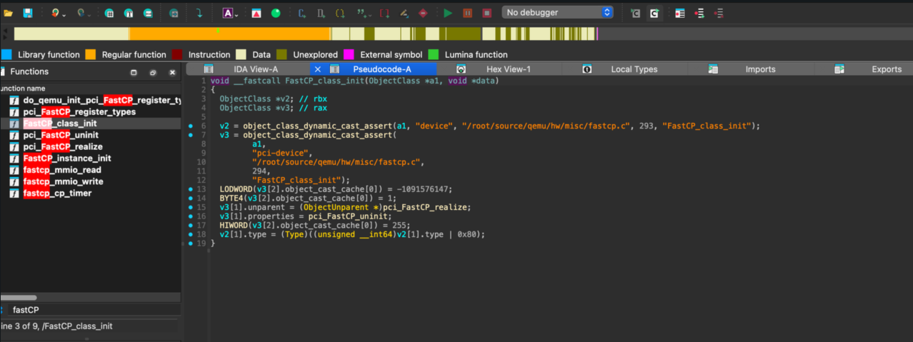
The relevant class initialization looked like this:
void __fastcall FastCP_class_init(ObjectClass *a1, void *data)
{
    ObjectClass *v2;
    ObjectClass *v3;

    v2 = object_class_dynamic_cast_assert(a1, "device",
                                          "/root/source/qemu/hw/misc/fastcp.c",
                                          293, "FastCP_class_init");
    v3 = object_class_dynamic_cast_assert(a1, "pci-device",
                                          "/root/source/qemu/hw/misc/fastcp.c",
                                          294, "FastCP_class_init");
    LODWORD(v3[2].object_cast_cache[0]) = 0xBEEFDEAD;
    BYTE4(v3[2].object_cast_cache[0]) = 1;
    v3[1].unparent = (ObjectUnparent *)pci_FastCP_realize;
    v3[1].properties = pci_FastCP_uninit;
    HIWORD(v3[2].object_cast_cache[0]) = 255;
    v2[1].type = (Type)((unsigned __int64)v2[1].type | 0x80);
}
From this code, we can identify:
vendor_id = 0xdeaddevice_id = 0xbeef
Then check the guest's PCI list:
00:01.0 Class 0601: 8086:7000
00:04.0 Class 00ff: dead:beef
00:00.0 Class 0600: 8086:1237
00:01.3 Class 0680: 8086:7113
00:03.0 Class 0200: 8086:100e
00:01.1 Class 0101: 8086:7010
00:02.0 Class 0300: 1234:1111
The custom device is therefore located at:
00:04.0 Class 00ff: dead:beef
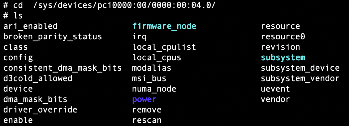
The corresponding sysfs directory is:
/sys/devices/pci0000:00/0000:00:04.0/
A directory listing shows files like these:
ari_enabled               firmware_node             resource
broken_parity_status      irq                       resource0
class                     local_cpulist             revision
config                    local_cpus                subsystem
consistent_dma_mask_bits  modalias                  subsystem_device
d3cold_allowed            msi_bus                   subsystem_vendor
device                    numa_node                 uevent
dma_mask_bits             power                     vendor
driver_override           remove
enable                    rescan
6.1 Sysfs PCI Device Path
/sys/devices/pci0000:00/0000:00:04.0/
|           |         |   |  |  `-- Function number, 0-7
|           |         |   |  `----- Device number, 0-31
|           |         |   `-------- Bus number, 0-255
|           |         `------------ Domain number, 0-65535
|           `---------------------- PCI root bus domain
`---------------------------------- sysfs root
Here:
pci0000:00is PCI domain0000, bus00.0000:00:04.0is the specific PCI device address:0000is the domain.00is the bus.04is the device number.0is the function number.
6.2 Basic Information Files
| File | Meaning | Example |
|---|---|---|
vendor |
Vendor ID | 0x8086, Intel |
device |
Device ID | 0x7113, PIIX4 PM |
subsystem_vendor |
Subsystem vendor ID | 0x1af4 |
subsystem_device |
Subsystem device ID | 0x1100 |
class |
Class code | 0x068000 |
revision |
Device revision | 0x03 |
irq |
IRQ number | 9 |
modalias |
Module alias | pci:v00008086d00007113... |
uevent |
udev event data | multi-line text |
6.3 Configuration Space
The config file exposes the raw PCI configuration space:
- 256 bytes for standard PCI.
- 4096 bytes for PCIe extended configuration space.
Example read:
hexdump /sys/devices/pci0000:00/0000:00:04.0/config
0000000 dead beef 0103 0010 0001 00ff 0000 0000
0000010 0000 fea0 0000 0000 0000 0000 0000 0000
0000020 0000 0000 0000 0000 0000 0000 1af4 1100
0000030 0000 0000 0040 0000 0000 0000 010b 0000
0000040 0005 0080 0000 0000 0000 0000 0000 0000
0000050 0000 0000 0000 0000 0000 0000 0000 0000
*
0000100
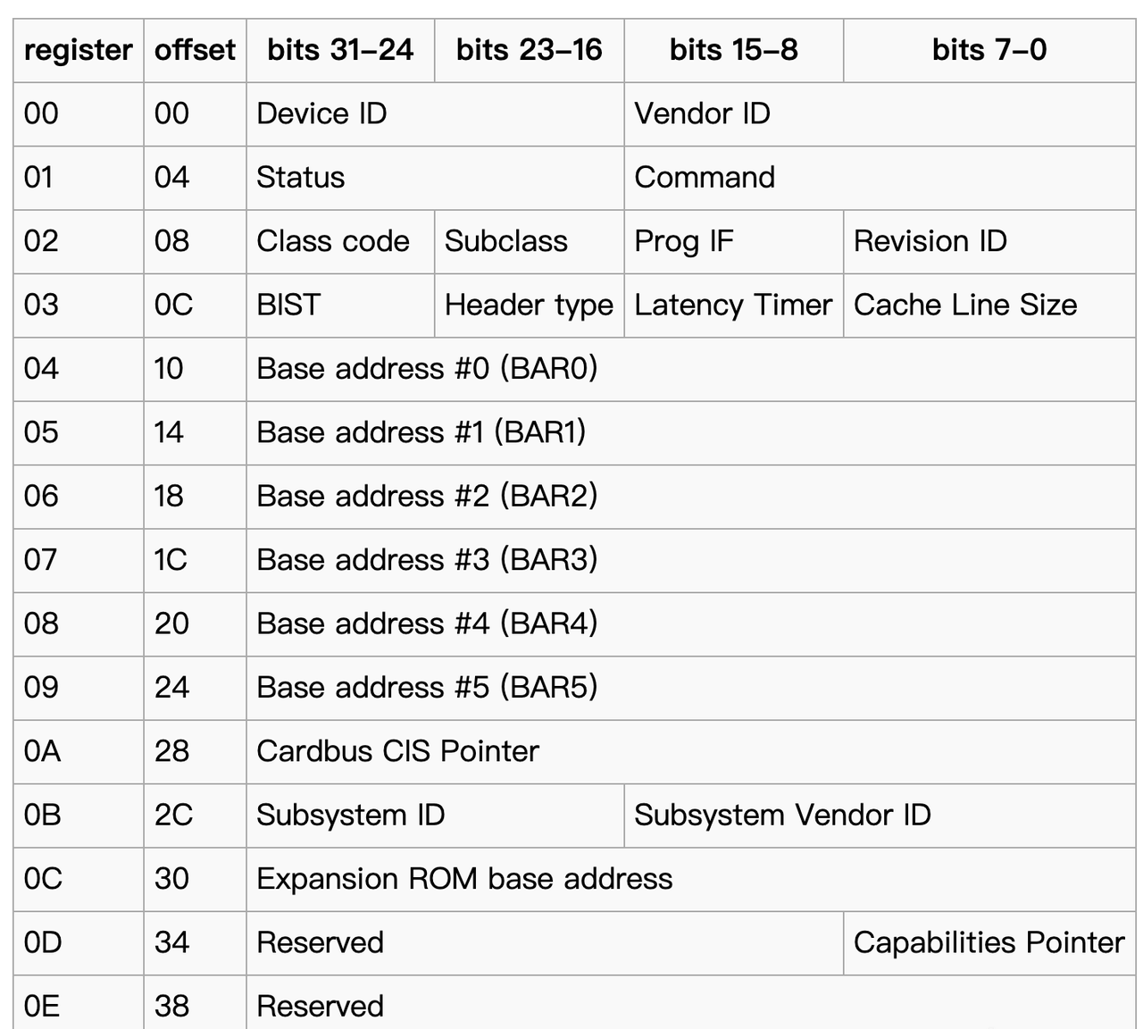
The first bytes decode as:
| Offset | Field | Value, little-endian | Meaning |
|---|---|---|---|
0x00 |
Vendor ID | 0xdead |
custom vendor ID |
0x02 |
Device ID | 0xbeef |
custom device ID, typical CTF magic value |
0x04 |
Command | 0x0103 |
command register |
0x06 |
Status | 0x0010 |
status register |
0x08 |
Revision ID | 0x01 |
device revision |
0x09 |
Class Code | 0xff0000 |
class code |
0x0c |
Cache Line Size | 0x00 |
cache-line size |
0x0d |
Latency Timer | 0x00 |
latency timer |
0x0e |
Header Type | 0x00 |
standard device header |
0x0f |
BIST | 0x00 |
built-in self-test |
BAR0 can be decoded from 0x0000fea0 in little-endian form:
0x0000fea0, little-endian -> 0xfea00000

0xfea00000 in binary:
1111 1110 1010 0000 0000 0000 0000 0000
                                      |
                                      `-- bit 0 = 0, Memory Space
The result is:
BAR0: MMIO
  address: 0xfea00000 - 0xfeafffff
  size:    1 MB
  type:    32-bit, non-prefetchable
  state:   enabled

BAR1-BAR5: unused
6.4 BAR Resource Files
| File | Meaning |
|---|---|
resource |
all BAR address ranges, text format |
resource0 |
raw BAR0 data, binary |
resource1 |
raw BAR1 data |
resource2 |
raw BAR2 data |
resource3 |
raw BAR3 data |
resource4 |
raw BAR4 data |
resource5 |
raw BAR5 data |
Example read:
cat /sys/devices/pci0000:00/0000:00:04.0/resource
0x00000000fea00000 0x00000000feafffff 0x0000000000040200
0x0000000000000000 0x0000000000000000 0x0000000000000000
0x0000000000000000 0x0000000000000000 0x0000000000000000
0x0000000000000000 0x0000000000000000 0x0000000000000000
0x0000000000000000 0x0000000000000000 0x0000000000000000
0x0000000000000000 0x0000000000000000 0x0000000000000000
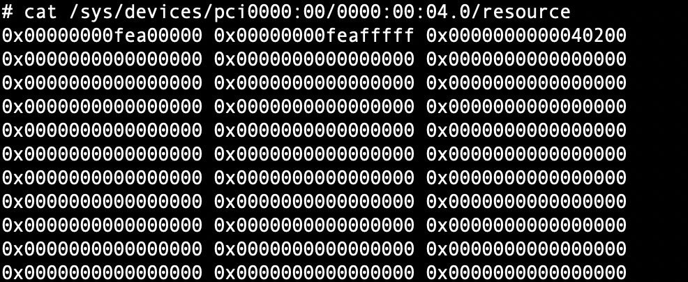
Each line has three fields:
start address, end address, flags
The last bit in the flags indicates the type. An even value means MMIO, and an odd value means PMIO. In this output only BAR0 is used:
0x00000000fea00000 0x00000000feafffff 0x0000000000040200  <- BAR0
0x0000000000000000 0x0000000000000000 0x0000000000000000  <- BAR1, unused
0x0000000000000000 0x0000000000000000 0x0000000000000000  <- BAR2, unused
...
The flag value can be interpreted as:
0x0000000000040200
              ||||
              |||`-- bit 0 = 0: Memory Space, MMIO rather than I/O
              ||`--- bit 1 = 0: 32-bit address
              |`---- bit 3 = 0: non-prefetchable
              `----- bit 9 = 1: 64-bit capable
For a memory BAR:
- Bit 0 is the region type and is always
0for memory space. - Bits 2-1 describe the locatability.
0means 32-bit address,2means 64-bit address, and1means the range is below 1 MB. - Bit 3 is the prefetchable bit.
0disables prefetching and1enables it. - Bits 31-4 hold the base address, aligned to 16 bytes.
6.5 Power Management and Driver Files
Power-management files include:
| File | Meaning |
|---|---|
power/control |
power-control mode, such as auto or on |
power/runtime_status |
runtime power state |
power/wakeup |
wakeup capability |
Driver-related files include:
| File or directory | Meaning |
|---|---|
driver |
symlink to the current driver |
driver_override |
force a specific driver |
Example:
readlink /sys/devices/pci0000:00/0000:00:01.3/driver
../../../../bus/pci/drivers/piix4_smbus
Other useful files are:
| File | Meaning | Operation |
|---|---|---|
enable |
enable or disable the device | echo 0/1 > enable |
remove |
remove the device | echo 1 > remove |
rescan |
rescan the device | echo 1 > rescan |
reset |
reset the device | echo 1 > reset |
broken_parity_status |
parity-error status | read |
d3cold_allowed |
allow D3cold power state | read/write |
msi_bus |
MSI bus support | read/write |
numa_node |
NUMA node | read |
consistent_dma_mask_bits |
DMA mask width | read |
7. Notes on MMIO and PMIO Access
The original draft ended with this section title as a placeholder. The concrete MMIO access flow has already been covered above: guest memory instructions trap into KVM, QEMU translates the physical address through AddressSpace and FlatView, and the final operation is dispatched through the MemoryRegionOps callback registered by the virtual PCI device.
PMIO follows the same high-level idea, but the guest uses port I/O instructions and the request is resolved through QEMU's I/O address space instead of the memory address space.